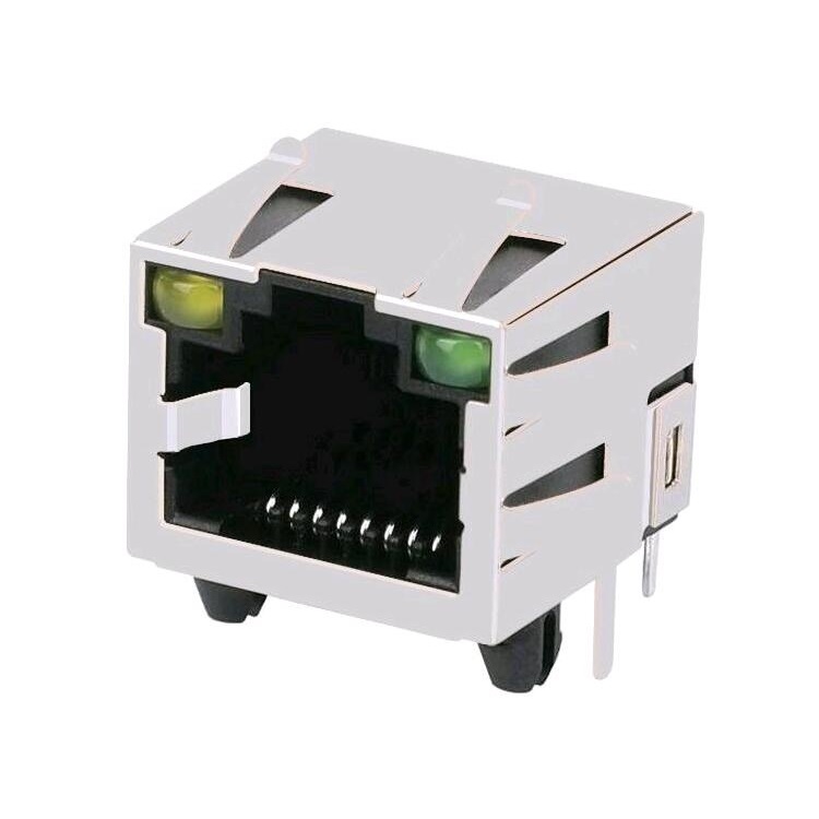
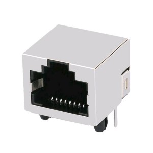
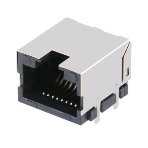
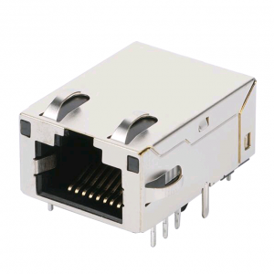
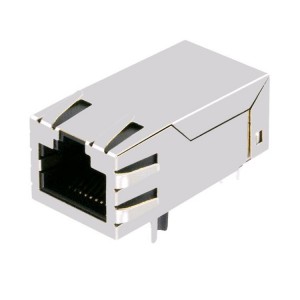
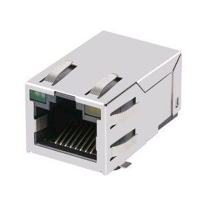
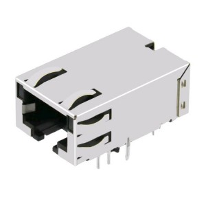
Tab-Up 1×1 Port 8P/8C Tab-Up Shielded RJ45 Ethernet Connectors 6116615-6 1116173-4
Tab-Up 1×1 Port 8P/8C Tab-Up Shielded RJ45 Ethernet Connectors 6116615-6 1116173-4
| Categories | Connectors, Interconnects |
| Modular Connectors - Jacks | |
| Application-LAN | ETHERNET(NoN POE) |
| Connector Type | RJ45 |
| Number of Positions/Contacts | 8p8c |
| Number of Ports | 1×1 |
| Applications Speed | RJ45 Without Magnetics |
| Mounting Type | Through Hole |
| Orientation | 90° Angle (Right) |
| Termination | Solder |
| Height Above Board | 13.40 mm |
| LED Color | With LED |
| Shielding | Shielded, EMI Finger |
| Features | Board Guide |
| Tab Direction | UP |
| Contact Material | Phosphor Bronze |
| Packaging | Tray |
| Operating Temperature | -40°C ~ 85°C |
| Contact Material Plating Thickness | Gold 6.00µin/15.00µin/30.00µin/50.00µin |
| Shield Material | Brass |
| Housing Material | Thermoplastic |
| RoHS Compliant | YES-RoHS-5 WIth Lead in Solder Exemption |
There are five conditions for model analysis
1. Multi-line model (MLM): Suitable for multi-pin RJ, including touch components, coupling between touch and touch, coupling between touch and shielding, coupling between pads, etc. In addition to the parameters imitated by SLM, it can also be used to imitate crosstalk and ground bounce.
2. Single wire model (SLM): Suitable for single wire in RJ, such as high-speed signal transmission line, which can be used to simulate reflection, delay and offset, attenuation and signal transmission quality.
3.S parameter model: mainly used in the frequency domain, which can imitate throughput and crosstalk. Through time domain conversion, impedance, crosstalk, transmission delay and eye diagrams can occur.
4. IBIS model: It is a way to quickly and accurately model the I/O BUFFER based on the V/I curve, supporting all types of RJ and a variety of different RJ modeling, such as differential and unbalanced signaling, SLM (without Coupling), MLM (coupling), model cascading, board-to-board and board-to-cable, etc.
5. SPICE model: It is a ubiquitous circuit-level simulation program. The components in the analyzed circuit can include resistance, capacitance, inductance, mutual inductance, independent voltage source, independent current source, various linear controlled sources, transmission lines, and active semiconductors equipment.


